

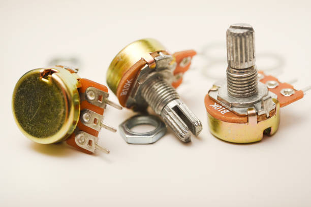
When sourcing a carbon film potentiometer, procurement engineers may hesitate when they see a ±20% resistance tolerance. Compared with precision potentiometers rated at ±5% or ±1%, the specification can appear inaccurate. However, ±20% potentiometer tolerance does not automatically mean poor performance. For many control applications, especially voltage-divider circuits, the actual impact of absolute resistance variation can be much smaller than expected.
The key is to evaluate tolerance according to the circuit configuration and application. In a three-terminal voltage-divider configuration, the output primarily depends on the ratio between the resistance sections. In a two-terminal rheostat configuration, the absolute resistance value has a more direct effect on circuit behavior. For applications such as gaming steering wheels and audio volume controls, a standard carbon film potentiometer can often provide a practical balance between performance and cost. Precision applications may require ±10%, ±5%, or tighter specifications.
What Does ±20% Potentiometer Tolerance Actually Mean?
Potentiometer tolerance describes the allowable deviation between the specified resistance value and the actual resistance value.
For example, consider a potentiometer rated at:
10 kΩ ±20%
Its total resistance may theoretically fall within:
8 kΩ to 12 kΩ
This does not mean that the control position is automatically 20% inaccurate.
That distinction is important.
The resistance tolerance describes the absolute resistance value, not necessarily the accuracy of the control output across the entire adjustment range.
Tolerance Is Not the Same as Control Accuracy
Procurement teams sometimes use resistance tolerance as a quick indicator of overall potentiometer precision.
However, a potentiometer has several performance parameters that should be evaluated separately:
- Total resistance tolerance
- Resistance taper
- Linearity
- Contact resistance
- Mechanical travel
- Electrical travel
- Repeatability
- Temperature coefficient
- Rated power
- Operating life
Therefore, a ±20% resistance tolerance should not be interpreted as “the potentiometer is 20% inaccurate.”
The circuit determines how much the resistance variation actually affects system performance.
Why Carbon Film Potentiometers Commonly Use ±20% Tolerance
Carbon film potentiometers are widely used in applications where cost efficiency, practical control performance, and reliable operation are more important than extremely tight resistance accuracy.
The resistance element uses a carbon-based resistive track, providing a practical solution for general-purpose adjustment and control applications.
A Wider Tolerance Can Support Cost-Effective Production
Tighter resistance tolerances generally require more controlled resistance manufacturing and selection processes.
For applications that do not require a highly precise absolute resistance value, specifying a tighter tolerance can increase component cost without delivering a meaningful improvement in system performance.
This is why buyers should avoid automatically selecting a ±1% or ±5% potentiometer simply because the tolerance specification looks better.
The correct question is:
Does the application actually benefit from tighter resistance tolerance?
Voltage Divider vs Rheostat: Why Circuit Configuration Matters
The effect of potentiometer resistance tolerance depends strongly on how the component is connected.
There are two common configurations:
- Three-terminal voltage divider
- Two-terminal rheostat
Understanding the difference is essential for procurement decisions.
Three-Terminal Potentiometer as a Voltage Divider
In a voltage-divider configuration, the potentiometer uses three terminals:
- Terminal 1: Resistive track end
- Terminal 2: Wiper
- Terminal 3: Opposite track end
The output voltage is determined primarily by the position of the wiper and the ratio between the upper and lower resistance sections.
A simplified relationship is:
Vout ≈ Vin × R₂ / (R₁ + R₂)
If the entire resistive track changes proportionally because of manufacturing tolerance, the ratio can remain approximately similar.
This is why total resistance tolerance can have a relatively limited effect on the output voltage in many voltage-divider applications.
Why This Matters for Procurement
Consider a 10 kΩ potentiometer with ±20% tolerance.
The actual total resistance could vary substantially from one component to another.
However, if the resistance track maintains the intended distribution along its travel, the wiper position can still provide a useful proportional control signal.
This makes general-purpose potentiometers suitable for applications where the user needs to adjust a parameter rather than establish a highly accurate absolute resistance.
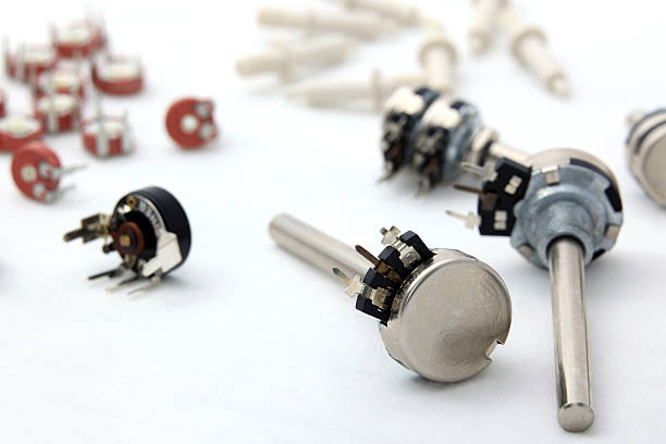
Gaming Steering Wheels Are a Typical Proportional Control Application
Gaming steering wheels provide a useful example.
The potentiometer can translate mechanical rotation into an electrical signal that the control system interprets as steering position.
The system is primarily interested in:
How far has the control moved?
rather than:
Is the total resistance exactly 10,000 Ω?
Why ±20% Can Be Acceptable
Suppose two steering-wheel potentiometers have slightly different total resistance values.
If both provide a stable and predictable voltage change across their mechanical travel, the electronic system can interpret the wiper position as a steering command.
In this type of application, the absolute resistance value may be less critical than:
- Stable electrical output
- Smooth mechanical movement
- Suitable resistance track characteristics
- Repeatable wiper behavior
- Appropriate mechanical angle
- Long operating life
Therefore, a carbon film potentiometer with ±20% tolerance may provide sufficient performance for a cost-sensitive gaming control application, depending on the circuit design.
Audio Volume Control Is Another Common Example
Audio volume controls also demonstrate why resistance tolerance should not be evaluated in isolation.
A potentiometer is often used to adjust the signal level supplied to an amplifier or audio circuit.
The user is controlling:
Relative signal level
rather than demanding an exact absolute resistance at every position.
Taper Can Matter More Than Total Resistance Tolerance
For audio applications, the resistance taper can be particularly important.
An audio-taper potentiometer is designed to provide a response that better matches how human hearing perceives changes in loudness.
This means a buyer should not focus only on:
10 kΩ ±20%
or
50 kΩ ±20%
The procurement specification may also need to define:
- Taper
- Mechanical rotation angle
- Shaft configuration
- Mounting type
- Rated power
- Contact resistance
- Operating life
- Environmental conditions
In many audio control applications, these parameters can have a greater practical impact than simply tightening the total resistance tolerance.
When ±20% Tolerance May Not Be Enough
Although ±20% can work well for many general-purpose control applications, it is not appropriate for every circuit.
The key question is whether the circuit depends on the absolute resistance value.
Two-Terminal Rheostat Configuration
When a potentiometer operates as a rheostat, only two terminals are used.
The component functions as a variable resistor.
In this configuration, the resistance value directly influences the circuit.
If a circuit requires a specific resistance range to establish current, bias, timing, or another electrical parameter, total resistance tolerance becomes more important.
Example: Precision Bias Adjustment
Imagine a circuit that uses a potentiometer to establish a sensitive bias point.
If the expected resistance range is critical to the circuit’s operating point, a ±20% total resistance variation may create too much uncertainty.
In this situation, the buyer should consider a tighter tolerance such as:
- ±10%
- ±5%
- ±2%
- ±1%
The appropriate value depends on the circuit’s actual tolerance budget.
When Should Buyers Choose ±10% or ±5%?
The decision should be based on engineering requirements rather than the idea that “tighter is always better.”
Choose ±20% for General Proportional Control
A standard tolerance may be appropriate when the potentiometer is mainly used for:
- User controls
- Audio volume adjustment
- Gaming controls
- General interface adjustment
- Non-critical voltage-divider circuits
- Cost-sensitive consumer electronics
Consider ±10% for More Controlled Resistance Requirements
A tighter specification may make sense when the potentiometer’s total resistance begins to influence system calibration or circuit behavior more significantly.
Consider ±5% or Tighter for Precision Applications
Precision resistance tolerance is more appropriate when the potentiometer is used for:
- Calibration
- Precision bias adjustment
- Measurement circuits
- Sensitive analog reference settings
- Circuit parameters with narrow allowable resistance ranges
The final selection should always consider the complete electrical design.
A Simple Procurement Decision Framework
Procurement engineers can use a simple decision process when evaluating carbon film potentiometer tolerance.
Step 1: Identify the Circuit Configuration
Ask whether the potentiometer operates as:
Voltage divider → tolerance may have a relatively smaller impact.
Rheostat → absolute resistance tolerance becomes more important.
Step 2: Identify What the System Measures
If the system measures relative position or user adjustment, a wider resistance tolerance may be acceptable.
If the system depends on an accurate resistance value, tighter tolerance may be necessary.
Step 3: Define the Required Electrical Accuracy
Do not specify ±5% or ±1% simply because it appears more precise.
Instead, determine the maximum resistance variation the circuit can tolerate.
Step 4: Consider Other Potentiometer Specifications
Resistance tolerance is only one part of the specification.
Also evaluate:
- Resistance value
- Taper
- Linearity
- Mechanical angle
- Shaft type
- Mounting method
- Contact resistance
- Rated power
- Operating temperature
- Expected mechanical life
Step 5: Balance Accuracy and Cost
The final component should meet the electrical requirements without unnecessarily increasing the BOM cost.
This is especially important for high-volume applications such as gaming peripherals and consumer audio equipment.
How to Calculate the Worst-Case Resistance Range
Procurement engineers can quickly estimate the potential resistance range using the tolerance specification.
For a potentiometer rated at R ± T%:
Minimum resistance = R × (1 − T)
Maximum resistance = R × (1 + T)
For example, a 10 kΩ potentiometer with ±20% tolerance has:
Minimum = 10 kΩ × 80% = 8 kΩ
Maximum = 10 kΩ × 120% = 12 kΩ
For a ±5% version:
Minimum = 9.5 kΩ
Maximum = 10.5 kΩ
The ±5% component clearly provides tighter absolute resistance control.
But that does not automatically mean it produces a better user control.
The circuit determines whether that additional precision creates measurable system value.
Why Procurement Engineers Should Avoid Over-Specifying Potentiometers
Over-specification is a common source of unnecessary component cost.
If a gaming controller only needs stable proportional position detection, specifying a ±1% potentiometer may provide little practical benefit compared with a suitable general-purpose model.
Similarly, if an audio control circuit can tolerate the component’s resistance variation, paying for unnecessarily tight tolerance may increase the BOM cost without improving the user experience.
Lower Tolerance Cost Does Not Mean Lower Product Quality
A component with a wider tolerance can still be the correct engineering choice.
The objective is not to purchase the smallest tolerance available.
The objective is to purchase:
the lowest-cost component that reliably satisfies the circuit requirements.
This principle is especially important for OEM and high-volume purchasing.
±20% Is Not “Low Precision” Until the Application Says So
A ±20% potentiometer tolerance should not be judged independently from the circuit.
For a three-terminal voltage-divider application, the output can depend primarily on the resistance ratio and wiper position. This makes a standard carbon film potentiometer suitable for many general-purpose control applications.
For a two-terminal rheostat application, however, the absolute resistance value has a more direct influence on circuit behavior. Precision biasing and calibration circuits may therefore require ±10%, ±5%, or tighter tolerance.
For procurement engineers, the most practical rule is simple:
Use ±20% when the application tolerates wider absolute resistance variation. Upgrade the tolerance when the circuit requires tighter resistance control.
The best potentiometer is not necessarily the one with the smallest tolerance.
It is the one that meets the application’s electrical, mechanical, reliability, and cost requirements without unnecessary over-specification.
FAQ About Carbon Film Potentiometer Tolerance
Is ±20% tolerance normal for carbon film potentiometers?
Yes. ±20% is a commonly used tolerance specification for general-purpose carbon film potentiometers. Buyers should evaluate it according to the application rather than treating it as an automatic indication of poor quality.
Does ±20% tolerance mean the potentiometer is 20% inaccurate?
No. Resistance tolerance describes the possible variation in total resistance. It does not mean the control output or user adjustment is automatically 20% inaccurate.
Is ±20% suitable for gaming steering wheels?
It can be suitable for many gaming steering-wheel designs where the potentiometer provides proportional position feedback. The complete circuit design, mechanical travel, linearity, and repeatability should also be evaluated.
Is ±20% suitable for audio volume controls?
It can be suitable for many general-purpose audio volume controls. Taper, channel matching, mechanical performance, and circuit design may be more important than simply tightening total resistance tolerance.
When should I choose a ±5% potentiometer?
Consider ±5% when the potentiometer’s absolute resistance has a meaningful effect on circuit calibration, biasing, or another precision electrical parameter.
Is ±1% always better than ±20%?
No. ±1% provides tighter resistance control, but it may add cost without providing practical benefits in applications that tolerate wider resistance variation.
What is more important than potentiometer tolerance?
Depending on the application, buyers should also consider taper, linearity, contact resistance, mechanical angle, operating life, rated power, temperature range, and circuit configuration.
Can Fanrui provide customized potentiometers?
For OEM and wholesale projects, buyers can specify electrical and mechanical requirements such as resistance value, tolerance, taper, shaft configuration, mounting structure, and other application-specific parameters.


