Volume Knob Crackling Noise: Causes, Testing Methods, and Potentiometer QC Standards
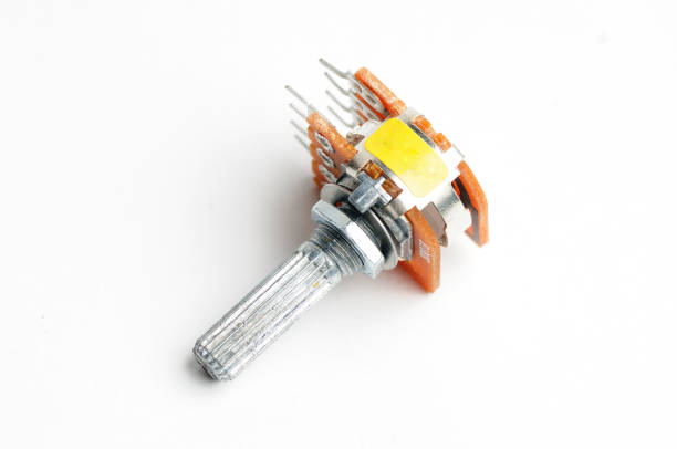
For audio equipment manufacturers, mixing console builders, and gaming peripheral integrators, volume knob crackling noise is a common quality concern. Users may hear scratching, popping, or intermittent noise when turning a volume control, even when the device otherwise operates normally.
This issue often originates from unstable electrical contact between the potentiometer wiper and resistive track. Contamination, oxidation, track wear, or insufficient wiper pressure can contribute to resistance fluctuations. Mechanical problems, such as inconsistent shaft torque, may also indicate manufacturing or assembly issues.
For B2B procurement teams and quality assurance (QA) engineers, the key is to distinguish component defects from normal wear, circuit-level noise, and application-related problems. A structured inspection process should combine mechanical evaluation, resistance testing, and dynamic contact resistance variation (CRV) measurement.
1. What Causes Volume Knob Crackling Noise?
A potentiometer controls a circuit by moving a wiper across a resistive track. When electrical contact becomes unstable during rotation, the resulting resistance fluctuations can produce audible crackling or scratching.
However, not every noise heard during volume adjustment originates from a defective potentiometer. Amplifier design, grounding, DC voltage across the potentiometer, contamination introduced during assembly, and other circuit conditions may also contribute.
The following table helps QA teams identify potential causes and determine the appropriate investigation.
| Symptom | Possible Physical Cause | Recommended Quality Control Action |
|---|---|---|
| Crackling in a new component | Contamination, oxidized contacts, inconsistent wiper pressure, or track defects | Inspect incoming components and verify dynamic noise performance |
| Scratching after extended use | Resistive track wear, contact wear, or accumulated debris | Compare cycle count and electrical performance with rated service life |
| Intermittent signal or dead zones | Oxidation, weak wiper contact, substrate damage, or intermittent open circuits | Perform a full-travel resistance sweep and contact inspection |
| Uneven rotational torque | Inconsistent lubricant distribution, shaft misalignment, or mechanical tolerance variation | Measure torque consistency and verify mechanical specifications |
| Noise only after installation | Soldering residue, assembly contamination, circuit bias, grounding, or amplifier interaction | Test the component separately and then evaluate the assembled circuit |
These symptoms indicate possible causes rather than definitive diagnoses. A component should be classified as defective only after testing against its specification and investigating relevant circuit or assembly conditions.
2. How to Test a Potentiometer for Crackling Noise
A practical incoming quality control (IQC) process uses three complementary checks: mechanical torque inspection, electrical resistance testing, and dynamic noise measurement.
Step 1: Inspect Shaft Rotation and Torque Consistency
Before electrical testing, rotate the potentiometer shaft through its specified mechanical travel.
Check for:
- Smooth, consistent rotational torque.
- Unexpected stiffness, looseness, or sudden torque changes.
- Abnormal shaft wobble or mechanical play.
- Correct end-stop behavior and specified rotational angle.
Do not assume every potentiometer supports either 300° or 360° of rotation. Actual travel depends on the component design and datasheet.
Sudden changes in rotational feel may indicate mechanical tolerance issues, lubricant distribution problems, or damage. However, torque variation alone does not prove that the electrical contact is unstable. Mechanical and electrical results should be evaluated together.
Step 2: Measure Resistance Changes with a Digital Multimeter
A digital multimeter can identify basic continuity problems and abnormal resistance changes during shaft rotation.
Recommended procedure:
- Disconnect power from the circuit and isolate the potentiometer as needed to avoid parallel circuit paths affecting the measurement.
- Identify the two outer terminals and the center wiper terminal using the component datasheet.
- Measure total resistance between the two outer terminals to check whether it falls within the specified nominal resistance tolerance.
- Connect the multimeter between the wiper and one outer terminal.
- Slowly rotate the shaft across its full electrical travel while monitoring the reading.
- Repeat the measurement between the wiper and the other outer terminal if needed.
The resistance should change in accordance with the potentiometer’s specified taper. Sudden discontinuities, intermittent open-circuit readings, or unexpected dead zones may indicate a contact or resistive-track problem.
How to Check Linear and Audio Taper
Different potentiometer tapers produce different resistance-versus-angle relationships.
| Potentiometer Type | Expected Resistance Behavior | QA Consideration |
|---|---|---|
| Linear taper, often marked B | Resistance changes approximately proportionally with shaft position | Compare measured values with the specified resistance-angle curve |
| Audio or logarithmic taper, often marked A | Resistance changes nonlinearly with shaft position | Use the manufacturer’s taper curve rather than expecting proportional changes |
Taper letter conventions can vary by manufacturer and market. Confirm the component’s actual taper specification before setting acceptance limits.
A multimeter is useful for screening basic electrical continuity, but it may not capture brief, high-speed resistance fluctuations that cause audible crackling. Passing a static resistance test does not guarantee low rotational noise.
Step 3: Perform Contact Resistance Variation (CRV) Testing
Contact resistance variation (CRV) testing evaluates electrical instability while the potentiometer rotates. It is more suitable than a standard multimeter for assessing intermittent contact disturbances.
A typical test setup uses a controlled measurement current and monitors the voltage response as the shaft moves. Temporary resistance changes appear as voltage fluctuations, which can be recorded and evaluated using suitable measurement equipment.
A typical evaluation process includes:
- Apply the test current and electrical connections specified by the applicable test method.
- Rotate the shaft at a controlled speed through the specified travel.
- Record the electrical response throughout the movement.
- Identify spikes, interruptions, or other deviations.
- Compare the results with the component datasheet or agreed supplier acceptance criteria.
An oscilloscope, dedicated noise measurement system, or suitable potentiometer test fixture may be used depending on the required sensitivity and test method.
The original proposed CRV target of 1%–3% of nominal resistance can serve as an initial discussion point for supplier qualification. It should not be treated as a universal acceptance limit. The applicable definition of CRV, measurement circuit, test current, rotation speed, and calculation method must be agreed upon before applying a numerical threshold.
3. Recommended Potentiometer IQC Inspection Workflow
For B2B buyers, a repeatable inspection workflow helps standardize incoming acceptance and supplier corrective actions.
| Inspection Stage | Test Method | What to Verify | Acceptance Basis |
|---|---|---|---|
| 1. Visual inspection | Magnified visual examination | Visible contamination, damage, corrosion, or shaft defects | Approved sample and component specification |
| 2. Mechanical inspection | Manual or instrumented rotation test | Smooth rotation, torque consistency, end stops, and mechanical play | Datasheet and mechanical drawing |
| 3. Total resistance | Multimeter or resistance meter | Nominal resistance and tolerance | Supplier datasheet |
| 4. Taper and continuity | Resistance sweep across shaft travel | Expected taper, continuity, and absence of abnormal interruptions | Resistance-angle curve and test procedure |
| 5. Dynamic noise | CRV measurement or an agreed noise test | Transient contact disturbances and resistance instability | Approved CRV limits and test conditions |
| 6. Application validation | Test in the assembled product | Audible noise, signal stability, and circuit interaction | End-product performance requirements |
For higher-risk applications, QA teams should also define sampling frequency, sample size, retest rules, failure classification, and corrective-action requirements. These details should be documented in the incoming inspection plan rather than left to individual inspectors.
4. How to Define Potentiometer Rotational Life
Rotational life describes the number of specified mechanical operating cycles a potentiometer can withstand while meeting the manufacturer’s defined performance requirements.
A cycle may involve moving the shaft from one end of its travel to the other and returning it to the starting position. However, the exact cycle definition, rotation speed, load conditions, and test environment must follow the relevant specification.
During or after life testing, manufacturers may evaluate:
- Total resistance drift.
- Contact resistance variation or rotational noise.
- Electrical continuity throughout the travel.
- Shaft torque and mechanical integrity.
- Changes in taper performance, where specified.
The original article identifies a possible resistance drift criterion of ±15% and commercial rotational-life ranges of 10,000–50,000 cycles, with higher-grade products potentially rated at 100,000–1,000,000 or more cycles. These figures should be treated as illustrative ranges from the source material, not guaranteed ratings for every carbon-film potentiometer.
Actual service life depends on construction, resistive-track materials, operating conditions, test method, and the manufacturer’s published rating. Procurement teams should request the applicable datasheet and life-test report rather than compare products by cycle count alone.
5. How to Prevent Volume Knob Crackling in Finished Products
Component-level inspection is important, but the final user experience also depends on circuit design and assembly quality.
For audio equipment and gaming peripherals, consider the following preventive measures:
- Specify electrical noise limits: Define the required CRV or rotational-noise performance using an agreed test method.
- Control assembly contamination: Review soldering, cleaning, handling, and storage processes where contamination may affect contact performance.
- Validate the installed circuit: Test the potentiometer in the actual circuit to identify grounding, DC bias, amplifier, or assembly-related noise.
- Match the component to the application: Consider rotational frequency, expected operating cycles, environmental exposure, resistance value, and taper.
- Track field failures: Record failure rates, operating conditions, lot numbers, and supplier corrective actions to identify recurring patterns.
If crackling appears only after installation, compare the isolated component’s performance with the assembled product. This helps distinguish a potentiometer defect from a circuit-level or assembly-related problem.
6. B2B Procurement FAQs
Q1: Is crackling in a brand-new potentiometer always an incoming material defect?
Not necessarily. Crackling during initial operation is a valid reason to investigate the component, but it does not automatically prove a manufacturing defect.
Potential causes include contaminated or oxidized contacts, inconsistent wiper pressure, resistive-track defects, soldering residue, and circuit-related interference. Test the component independently where practical, then compare the findings with the agreed supplier specifications.
Q2: Can a standard multimeter detect potentiometer crackling noise?
A multimeter can identify basic continuity problems and obvious resistance jumps during slow rotation. However, it may miss brief or high-frequency contact disturbances.
For more sensitive quality screening, use a suitable dynamic resistance or CRV test system and an agreed measurement procedure.
Q3: How should QA teams test linear taper and audio taper potentiometers?
Measure resistance between the wiper and an outer terminal while rotating the shaft. Compare the resulting resistance-versus-angle behavior with the manufacturer’s taper curve.
A linear taper should approximately follow a proportional relationship, while an audio taper follows a nonlinear curve. Do not apply the same acceptance curve to both types.
Q4: What CRV limit should buyers specify?
The appropriate limit depends on the potentiometer design, application, measurement method, and product requirements. The proposed 1%–3% range can be discussed during supplier qualification, but it should not be adopted as a universal standard without supporting specifications.
Request the supplier’s test method, acceptance limits, and representative test results before approving the component.
Q5: How many rotational cycles should a potentiometer withstand?
There is no single cycle count suitable for every application. Select a component based on the expected operating frequency, product service-life target, environmental conditions, and published life-test results.
Require suppliers to state how a cycle is defined and which electrical and mechanical criteria must still be met after testing.
Q6: What should buyers request from a potentiometer supplier?
At minimum, request the component datasheet, nominal resistance and tolerance, taper specification, mechanical travel and torque data, rotational-life rating, and relevant noise or CRV test results.
For high-volume or high-reliability programs, document the test conditions, acceptance limits, sampling plan, lot traceability, and corrective-action process in the supplier quality agreement.
Conclusion: Build a Repeatable Potentiometer Quality Standard
Volume knob crackling noise can result from unstable wiper contact, contamination, resistive-track wear, mechanical inconsistencies, or circuit-level factors. A reliable quality program therefore combines mechanical inspection, resistance and taper testing, dynamic CRV evaluation, and validation in the final application.
For audio equipment manufacturers, mixing console builders, and gaming peripheral integrators, the most effective procurement strategy is to define measurable acceptance criteria before mass production. Request verified test reports, confirm rotational-life ratings, and align supplier quality controls with the real operating conditions of the finished product.
Need support for a potentiometer sourcing project? Work with your component supplier to confirm resistance values, taper options, shaft specifications, rotational-life requirements, and rotational-noise acceptance criteria before finalizing a bulk order.