

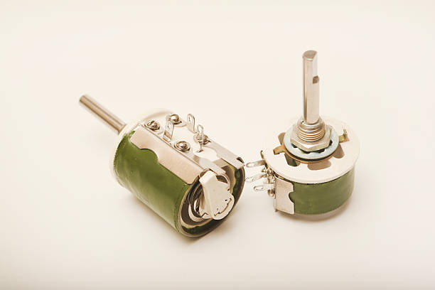
Gaming Steering Wheel Potentiometer Drift: Causes, Testing, and Calibration
When a gaming steering wheel drifts to one side, the potentiometer may not be physically damaged. In many cases, the problem involves firmware calibration, mechanical alignment, or a mismatch between the potentiometer’s electrical travel and the controller’s calibration range.
For gaming peripheral manufacturers, OEM buyers, and quality assurance engineers, identifying the actual cause before replacing components can reduce unnecessary service costs and warranty returns.
A systematic diagnosis of a gaming steering wheel potentiometer should begin with software recalibration, continue with electrical linearity testing, and finish with a review of component tolerances and mechanical installation.
What Causes Gaming Steering Wheel Potentiometer Drift?
A potentiometer converts shaft rotation into a changing electrical signal. The steering wheel’s microcontroller reads this signal and maps it to a steering position in the game.
If the electrical signal does not correspond correctly to the firmware’s expected center position, the game may register steering input even when the physical wheel appears centered.
Three common causes should be investigated.
1. Firmware Center Calibration Errors
Many steering wheel controllers use calibration data to identify the center position and the left and right travel limits.
If the controller initializes while the wheel is held off-center, or if stored calibration values become invalid, the calculated zero point may shift. The resulting symptom can resemble a faulty potentiometer even when its electrical output remains smooth.
A full-stroke recalibration is therefore a useful first diagnostic step, provided the device supports this procedure.
2. Mechanical Alignment and Travel Mismatch
The potentiometer’s shaft rotation, mounting position, mechanical stops, and effective electrical travel must work together.
A mismatch can cause the controller to interpret the physical center incorrectly or fail to use the expected portion of the potentiometer’s electrical range.
For example, a design specifying an effective electrical angle of 45∘±20%45^\circ \pm 20\% may permit a substantial difference in usable angular travel between production units. The actual impact depends on how the controller maps the measured signal to steering position.
3. Potentiometer Wear or Electrical Damage
Physical deterioration can also cause steering drift or unstable input. Potential failure mechanisms include:
- Wear or damage to the carbon resistive track.
- Oxidation or contamination affecting the wiper contact.
- Intermittent electrical contact.
- Localized dead zones or discontinuities in the resistance response.
Unlike a simple center offset, these problems may produce jitter, sudden signal changes, or inconsistent readings during shaft rotation.
Potentiometer Calibration Drift vs. Physical Failure
Before replacing a component, compare the observed symptoms with the following diagnostic indicators.
| Diagnostic dimension | Calibration or tolerance mismatch | Physical potentiometer failure |
|---|---|---|
| Typical symptom | Consistent steering offset with otherwise smooth movement | Jitter, intermittent input, sudden jumps, or dead zones |
| Electrical output | Smooth signal with an incorrectly mapped center | Discontinuous or unstable signal |
| Recalibration result | May resolve the issue if calibration is the cause | Usually does not eliminate genuine contact or track damage |
| Resistance sweep | Generally continuous, subject to the component’s specified response | May show abrupt changes, open circuits, or stagnant regions |
| Likely investigation area | Firmware mapping, mechanical alignment, or travel limits | Resistive track, wiper contact, wiring, or component damage |
These symptoms are diagnostic clues rather than definitive proof. Wiring faults, connector problems, controller input circuitry, and other mechanical issues can produce similar behavior.
How to Troubleshoot Gaming Steering Wheel Drift
Use the following three-step process to distinguish calibration problems from potential hardware failures.
Step 1: Perform a Full-Stroke Recalibration
Start with the controller’s supported calibration procedure before disassembling the steering wheel.
- Place the wheel in its specified neutral position.
- Check the manufacturer’s instructions for entering calibration mode.
- Move the wheel through its full permitted left-to-right travel.
- Allow the controller to record the center and travel limits, if supported.
- Test whether the steering input returns consistently to center.
If the drift disappears, the likely cause was a calibration or mapping issue. Confirm the result through repeated center-return tests.
If the problem persists, continue with electrical and mechanical inspection.
Important: Do not force the steering wheel beyond its mechanical stops or reset EEPROM calibration data unless the device’s service procedure permits it.
Step 2: Test Potentiometer Resistance Linearity
If recalibration does not solve the problem, inspect the potentiometer’s electrical response.
For a conventional three-terminal potentiometer, a resistance sweep can help identify discontinuities. First disconnect the component from the controller according to the manufacturer’s service instructions.
- Identify the wiper and resistive-track terminals using the component datasheet.
- Set a digital multimeter to resistance mode.
- Measure the appropriate terminal pairs.
- Rotate the shaft slowly across the specified mechanical travel.
- Record the resistance readings and look for abrupt jumps, interruptions, or dead zones.
A healthy conventional potentiometer should produce a continuous response consistent with its specified electrical characteristics. The response may not be perfectly linear unless the component is designed and specified as a linear-taper device.
Do not assume that wiper-to-ground resistance must always increase across the full sweep. The direction and measurement range depend on the terminal arrangement and shaft orientation.
How to interpret the results:
- Smooth, repeatable response: Investigate calibration data, mounting alignment, mechanical travel, wiring, and controller input mapping.
- Abrupt resistance changes or intermittent open circuits: Inspect the wiper contact, resistive track, terminals, and wiring before deciding whether replacement is necessary.
- Inconsistent readings only while connected: Check the measurement setup and controller circuitry, because in-circuit paths can affect resistance readings.
For production quality control, an oscilloscope or suitable data-acquisition system can also help evaluate the output voltage while the shaft moves. This is useful when the failure appears under dynamic operating conditions.
Step 3: Verify Angular Tolerance and Firmware Compatibility
If the resistance sweep is stable but the steering center remains incorrect, compare the component specifications with the controller’s calibration design.
Review these parameters:
- Mechanical rotation angle and physical stop positions.
- Effective electrical travel angle.
- Total resistance and resistance tolerance.
- Output voltage range and controller ADC input range.
- Firmware center calculation and endpoint mapping.
- Mechanical mounting tolerances and shaft coupling alignment.
- Software dead-band settings, if supported.
Consider the example specification of 45∘±20%45^\circ \pm 20\% effective electrical angle. The nominal value alone does not establish the actual center error, because effective travel variation does not necessarily translate directly into the same angular error at the wheel’s center.
The firmware’s mapping method, mounting geometry, and calibration procedure determine the final behavior.
For OEM production, a tighter resistance tolerance, such as ±10%\pm 10\%, may be worth evaluating. However, resistance tolerance and angular tolerance describe different characteristics. A tighter resistance tolerance does not automatically guarantee more accurate steering-center detection.
Where repeatable center positioning is important, evaluate the full component specification rather than relying on one tolerance value.
How Should OEM Buyers Specify a Gaming Steering Wheel Potentiometer?
For gaming peripheral manufacturers, component selection should account for both the potentiometer’s electrical characteristics and the controller’s calibration strategy.
| Procurement parameter | What buyers should verify | Why it matters |
|---|---|---|
| Effective electrical angle | Nominal angle, tolerance, and usable signal range | Helps match the component to firmware mapping |
| Mechanical rotation angle | Shaft travel and stop positions | Prevents mechanical and electrical travel mismatch |
| Total resistance | Nominal resistance and permitted variation | Supports compatibility with the controller circuit |
| Resistance response | Linear or other specified taper; continuity across travel | Helps establish expected steering response |
| Wiper performance | Contact stability and resistance variation during movement | Reduces intermittent signals and jitter |
| Mechanical construction | Shaft dimensions, mounting geometry, and coupling | Supports repeatable assembly alignment |
| Operating durability | Rated rotational life and applicable test conditions | Helps assess suitability for repeated gaming use |
| Quality documentation | Datasheets, tolerance reports, and agreed inspection criteria | Supports incoming inspection and supplier consistency |
Should Buyers Request Custom Potentiometers?
Custom specifications may be appropriate when a standard component cannot meet the required travel, mounting, resistance, or durability requirements.
Possible customization options include shaft geometry, mounting dimensions, electrical angle, resistance value, and tolerance targets.
For high-volume production, buyers should also consider whether the supplier can maintain consistent specifications across batches and provide inspection data that matches the agreed acceptance criteria.
A practical qualification process includes sample testing, controller-level calibration trials, repeated center-return checks, and verification across multiple production samples.
Technical FAQs
1. What center offset is acceptable for a gaming steering wheel?
There is no universal center-offset limit that applies to every gaming steering wheel. The acceptable value depends on the product’s design requirements, firmware mapping, mechanical geometry, and intended steering precision.
A range such as ±1.5∘\pm 1.5^\circ to ±3.0∘\pm 3.0^\circ should be treated as a product-specific evaluation range, not a general manufacturing standard. Manufacturers should define the allowable offset and verify it through system-level testing.
2. Can a multimeter confirm that a steering wheel potentiometer is faulty?
A multimeter can identify some electrical problems, including discontinuities and intermittent open circuits during a resistance sweep. However, it cannot always reveal faults that occur only during dynamic operation or under the normal controller load.
If resistance readings appear normal but steering drift persists, inspect the output signal, wiring, mechanical alignment, and firmware calibration.
3. Is recalibration required after replacing a gaming steering wheel potentiometer?
Recalibration is recommended whenever the manufacturer’s service procedure requires it or the replacement changes the electrical or mechanical relationship between the shaft and controller.
A replacement component may differ in resistance, effective travel, or wiper position. The controller should therefore be checked to confirm that its center and travel limits match the installed component.
4. Does a tighter resistance tolerance prevent steering drift?
Not by itself. Resistance tolerance describes variation in the component’s total resistance, while steering drift can also result from angular tolerance, mechanical misalignment, firmware mapping, wiring, or wear.
Buyers should specify the electrical and mechanical characteristics that directly affect their design, then validate the complete steering system.
5. What should manufacturers test before approving a potentiometer batch?
A practical incoming inspection plan can include total resistance, resistance response across travel, electrical continuity, shaft dimensions, mechanical travel, and sample testing in the target controller.
Acceptance limits should be agreed with the supplier and based on the product’s engineering requirements rather than assumed industry-wide values.
Conclusion: Diagnose the System Before Replacing the Component
Gaming steering wheel drift does not always indicate a damaged potentiometer. A calibration mismatch or mechanical alignment issue can create a similar symptom, while genuine track or wiper deterioration may cause unstable electrical output.
For troubleshooting teams, the recommended sequence is straightforward: recalibrate the controller, test the potentiometer’s electrical response, and verify the component’s mechanical and electrical tolerances against the firmware design.
For OEM buyers, defining the complete interface between the potentiometer, mechanical assembly, and controller is more effective than relying on resistance tolerance alone.
Looking for a gaming steering wheel potentiometer for OEM production? Evaluate electrical travel, resistance specifications, mounting compatibility, durability, and batch consistency together to support reliable steering performance and repeatable manufacturing quality.


